Pre-requisites!
I'll be using these components:
- A standard ESP8266-12 on a breakout-board such as the one shown
- Three 4.7k resistors
- A 3v battery (I use a CR123a) for powering the ESP826612
- A DS1820 (I use the DO-92 packaged version below)
The following requirements should be met:
- All connections, including those on the The ESP 8266-12 on the breakout-board, are solid and conduct power as they should.
- The battery holds at least 2.8v of power.
- The ESP8266-12 has been programmed with the following sketch:
#include OneWire.h
#include DallasTemperature.h
#include ESP8266WiFi.h
#include ESP8266WiFiMulti.h
#include ESP8266HTTPClient.h
#define ONEWIRE_PIN 13
OneWire oneWire(ONEWIRE_PIN);
DallasTemperature sensors(&oneWire);
boolean TempSensorAvailable = false;
DeviceAddress TempSensor;
float tempCtry1;
float tempCtry2;
#define AP_SSID "your wifi-network name here<your-wifi-network-name-here>"
#define AP_PASSWORD "wifi password here<your-wifi-network-password-here>"
void setup() {
Serial.begin(74880);
sensors.begin();
Serial.print("Found ");
Serial.print(sensors.getDeviceCount(), DEC);
Serial.println(" OneWire device(s).");
Serial.print("Parasite power: ");
if (sensors.isParasitePowerMode()) Serial.println("ON");
else Serial.println("OFF");
if (!sensors.getAddress(TempSensor, 0)) {
Serial.println("No OneWire Device Found");
} else {
TempSensorAvailable = true;
Serial.println("OneWire Device Found");
sensors.setResolution(TempSensor, 12);
}
}
void loop() {
wifiConnect();
postTemperature();
<onewire .h=""><dallastemperature
.h=""><esp8266wifi .h=""><esp8266wifimulti
.h=""><esp8266httpclient
.h=""><your-wifi-network-name-here><your-wifi-network-password-here>
<onewire .h=""><dallastemperature
.h=""><esp8266wifi .h=""><esp8266wifimulti
.h=""><esp8266httpclient
.h=""><your-wifi-network-name-here>
<your-wifi-network-password-here>delay(60 * 1000);
}
void postTemperature()
{
sensors.requestTemperatures(); tempCtry1 = sensors.getTempC(TempSensor); sensors.requestTemperatures(); tempCtry2 = sensors.getTempC(TempSensor);
HTTPClient http;
http.begin("http://<your-http-post-endpoint-here>");
http.addHeader("Content-Type", "application/json");
String postMessagePart1 = String("{ 'sensorId' :
'L15-Out1', 'temperature' : '");
String postMessagePart2 = String("', 'postAttempts' : '");
String postMessagePart3 = String("', 'batteryVoltage' : '");
String postMessagePart4 = String("' }");
String postMessage = postMessagePart1 + ((tempCtry1+tempCtry2)/2) +
postMessagePart2 + retries + postMessagePart3 + vdd + postMessagePart4 ;
int httpCode = http.POST(postMessage);
Serial.print("http result:");
Serial.println(httpCode);
http.writeToStream(&Serial);
http.end();
if ( httpCode != 200 && httpCode != 201)
{
delay(1000);
postTemperature();
}
}
void wifiConnect()
{
Serial.print("Connecting to AP");
WiFi.begin(AP_SSID, AP_PASSWORD);
while (WiFi.status() != WL_CONNECTED) {
delay(1000);
Serial.print(".");
}
Serial.println("");
Serial.println("WiFi connected");
}
Don't forget to import the libraries into the Arduino IDE environment.
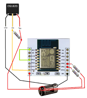
Given the above is in order, go ahead and connect the components as per the following picture:

- The RESET and GPIO16 pins should be connected - this enables the ESP 8266-12 to wake up from deep sleep mode.
- The GPIO0 and GPIO2 should be connected to VCC with a 4.7k resistor in the middle. This is to prevent a so-called 'zombie-mode', in which the ESP8266-12 has trouble waking up from deep sleep.
- The data-line and the VCC line of the DS1820 should be joined by a 4.7k resistor, or the temperature will not be read.
- The data-line of the DS1820 should be connected to the GPIO13-pin of the stand-alone ESP8266-12, as this corresponds with the "
#define ONEWIRE_PIN 13" statement of the code.
With the ESP connected like so, my ESP8266-12 happily does an HTTP post to my web-service every 60 seconds, before repeating the cycle.
You should put the ESP8266-12 into deep sleep mode if you power your thermometer via battery.
