The HID protocol serves as a foundational element for USB Input devices such as mice, keyboards, and hobby electronic project. In this article, we'll delve into the configuration of a STM32 board to serve as a starting point for creating various USB Input devices, as previously mentioned.
Prerequisite
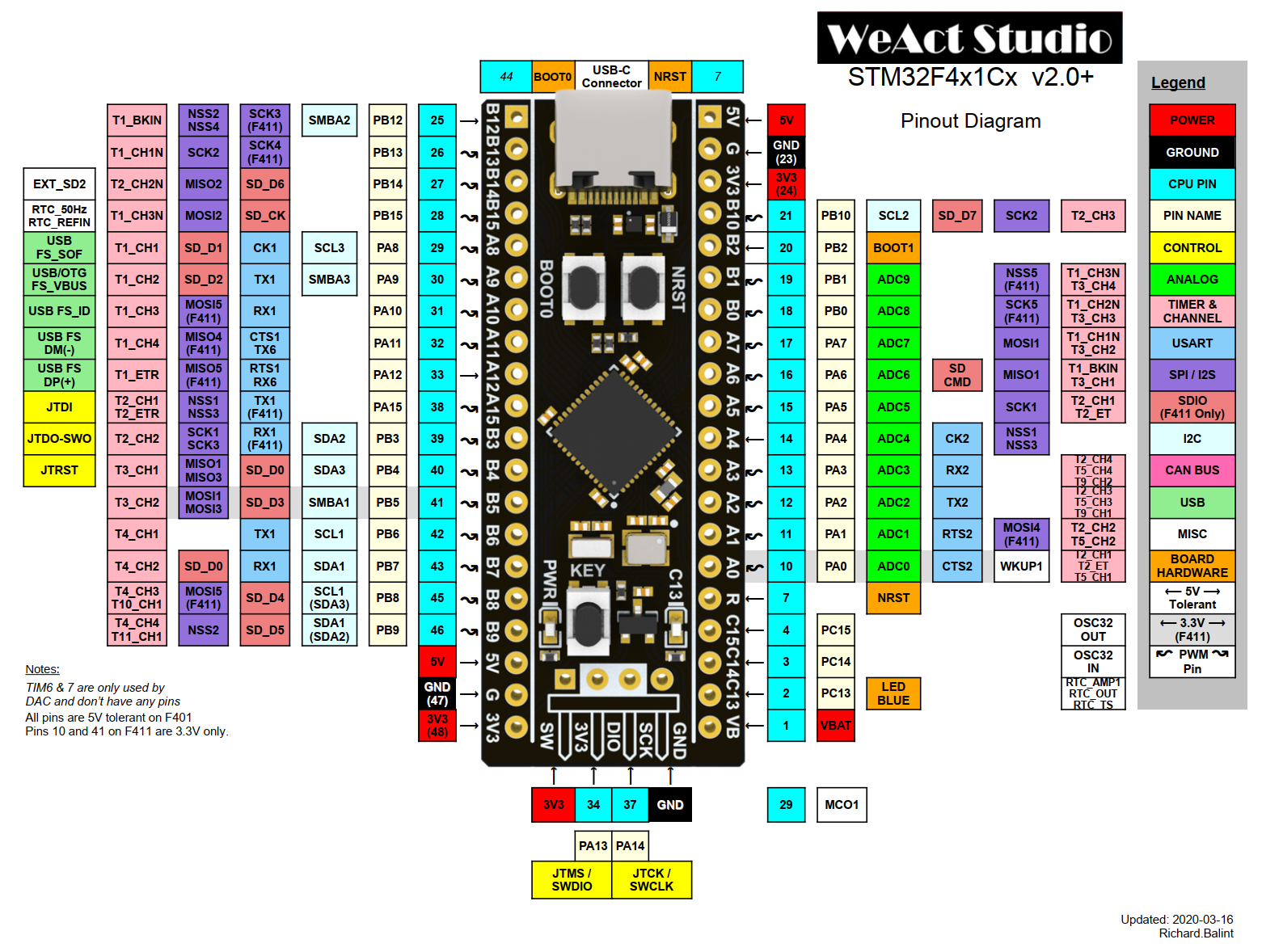
To get started, you'll need to install STM32CubeIDE and STM32CubeProg, after that you'll need to obtain an ST-LINK V2 device along with an STM32F411CEU6 board, commonly known as Black Pill Development Board.
Feature richness and performance comparison:
- Black pill > Blue/Red/Purple pill > Green pill > Arduino boards

Listing of Essential API's Functions
GPIO_PIN_SET and GPIO_PIN_RESET names come from SR Flip-flops (learnabout-electronics.org)
HAL_GPIO_WritePin()
void HAL_GPIO_WritePin(GPIO_TypeDef* GPIOx, uint16_t GPIO_Pin,
GPIO_PinState PinState);
HAL_GPIO_WritePin(GPIOE, LED1_Pin, GPIO_PIN_SET); HAL_GPIO_WritePin(GPIOE, LED1_Pin, GPIO_PIN_RESET);
HAL_GPIO_ReadPin()
GPIO_PinState HAL_GPIO_ReadPin(GPIO_TypeDef* GPIOx, uint16_t GPIO_Pin);

GPIO_PinState LED1_PinState = HAL_GPIO_ReadPin(GPIOE, LED1_Pin);
HAL_GPIO_WritePin(GPIOE, LED2_Pin, LED1_PinState);
HAL_GPIO_WritePin(GPIOE, LED3_Pin, LED1_PinState);
HAL_Delay()
void HAL_Delay(uint32_t Delay);
HAL_Delay(500);
Bootloader Programming
Inside STM32CubeIDE, create a new project with STM32F411CEU6 as Commerical Part Number


Then perform these actions in sequence:
- Next
- Project naming
- Finish
- Wait for the software packages download
You are now seeing the MCU chosen:

To be able to keep an eye on normal or programming mode, a LED can help that out.
Left click on the PB10 pin and choose GPIO_Output and in System Core tab, select the said pin and set its output level at high.


On the electronic board, physically attach a LED to B10 pin and ground it.
Then we have to setup a clock device (System Core tab)

After that, we can setup the USB feature inside Connectivity and Middleware tabs


We choose Custom HID class rather HID class since Custom HID class offer the possibility to read HID packet.
Switch on Clock Configuration tab and click on Resolve Clock Issues, then Ctrl-S to generate the code

Click near the hammer to choose Release in order to generate the binary file in elf format.

Grab your STM32 board and wire its back pins to the corresponding pins of ST-LINK V2:
3.3V to 3.3VSWCLK to SWCLK GND to GNDSWDIO to SWDIO
Once finished, connect the ST-LINK V2 to PC.
Inside STM32CubeProgrammer click on Connect button and on + button to access to Open File.

Select the *.elf file inside Release folder of the created STM32CubeIDE project then click on Download button, then plug the STM32 board on PC via the USB-C port.
To see the newly created device appear on windows, you just need to press NRST button onboard, you should see this, there is an error because the HID report descriptor has not been set.

Firmware Programming
Back in STM32CubeIDE, you would need to modify some data to prepare the device.
Inside \USB_DEVICE\App\usbd_desc.c
Update these defines with these new values:
#define USBD_VID                        0x0001
#define USBD_PID_FS                     0x0001
#define USBD_LANGID_STRING              1033
#define USBD_MANUFACTURER_STRING        "Manufacturer Name"
#define USBD_PRODUCT_STRING_FS          "Product Name"
#define USBD_CONFIGURATION_STRING_FS    "Configuration Name"
#define USBD_INTERFACE_STRING_FS        "Interface Name"
Inside \USB_DEVICE\App\usbd_custom_hid_if.c
Replace CUSTOM_HID_ReportDesc_FS[] with:
enum HID_Helper
{
IN_REPORT_ID = 0x02,
IN_REPORT_SIZE = 8,
IN_REPORT_COUNT = 2,
OUT_REPORT_ID = 0x01,
OUT_REPORT_SIZE = 8,
OUT_REPORT_COUNT = 2,
};
__ALIGN_BEGIN static uint8_t CUSTOM_HID_ReportDesc_FS[USBD_CUSTOM_HID_REPORT_DESC_SIZE]
__ALIGN_END =
{
0x06, 0x00, 0xFF,
0x09, 0x01,
0xA1, 0xFF,
0x15, 0x00,
0x26, 0xFF, 0x00,
0x85, IN_REPORT_ID,
0x75, IN_REPORT_SIZE,
0x95, IN_REPORT_COUNT,
0x09, 0x00,
0x81, 0x00,
0x85, OUT_REPORT_ID,
0x75, OUT_REPORT_SIZE,
0x95, OUT_REPORT_COUNT,
0x09, 0x00,
0x91, 0x00,
0xC0
};
To learn more about HID Report Descriptor, you can explore Human Interface Devices (HID) Information | USB-IF
Inside \Middlewares\ST\STM32_USB_Device_Library\Class\CustomHID\Src\usbd_customhid.c
Add the following code after USBD_CUSTOM_HID_SendReport():
uint8_t USBD_CUSTOM_HID_SendReport(USBD_HandleTypeDef* pdev, uint8_t* report, uint16_t len)
{
}
extern USBD_HandleTypeDef hUsbDeviceFS;
void HID_Send(uint8_t* Data, uint16_t Size)
{
USBD_CUSTOM_HID_SendReport(&hUsbDeviceFS, Data, Size);
}
Add the following code after USBD_CUSTOM_HID_ReceivePacket():
uint8_t USBD_CUSTOM_HID_ReceivePacket(USBD_HandleTypeDef *pdev)
{
}
void HID_Read(uint8_t* Data)
{
USBD_HandleTypeDef* pdev = &hUsbDeviceFS;
USBD_CUSTOM_HID_HandleTypeDef* hhid;
hhid = (USBD_CUSTOM_HID_HandleTypeDef *)pdev->pClassDataCmsit[pdev->classId];
memcpy(Data, hhid->Report_buf, USBD_CUSTOMHID_OUTREPORT_BUF_SIZE);
}
Now we're ready to start programming the firmware (also called App in this IDE).
Inside \Core\Src\main.c
Replace main() by this:
enum HID_Helper
{
RID_SIZE = 1,
IN_REPORT_COUNT = 2,
OUT_REPORT_COUNT = 2,
IN_REPORT_ID = 0x02,
OUT_REPORT_ID = 0x01,
};
uint8_t HostOutBuffer [RID_SIZE + OUT_REPORT_COUNT];
uint8_t HostInBuffer [RID_SIZE + IN_REPORT_COUNT ];
uint8_t DeviceOutBuffer[RID_SIZE + OUT_REPORT_COUNT];
uint8_t DeviceInBuffer [RID_SIZE + IN_REPORT_COUNT ];
int main(void)
{
HAL_Init();
SystemClock_Config();
MX_GPIO_Init();
MX_USB_DEVICE_Init();
while (1)
{
HID_Read(DeviceOutBuffer);
DeviceInBuffer[0] = IN_REPORT_ID;
DeviceInBuffer[1] = DeviceOutBuffer[1];
DeviceInBuffer[2] = DeviceOutBuffer[2];
HID_Send(DeviceInBuffer, RID_SIZE + IN_REPORT_COUNT);
HAL_Delay(500);
}
}
Now, we possess an STM32 board capable of acquiring data that can be configured from a PC, also known as the host device, and has the ability to transmit this data back to the host device.
Finally, we can rebuild and upload the new binary file to the STM32 board.
And for being able to interact with this board, we can use two tools.
A USB sniffer such as Busdog and a USB HID Communication Tool
FS means Full-Speed for USB spec:
LS  =  Low Speed  =   1.5 Mbps
FS  = Full Speed  =  12   Mbps
HS  = High Speed  = 480   Mbps
SS  = SuperSpeed  =   5   Gbps
SS+ = SuperSpeed+ =  10   Gbps
SS+ = SuperSpeed+ =  20   Gbps
History
- 16th July, 2021 : Initial version
