Great News! Your scrappy little space start-up just won a very competitive contract to populate Mars with hundreds of sensors to collect environmental and visual data! Bad News! It will take almost all the project budget to get the collection devices to the surface of Mars in the first place. You’re the lucky engineer tasked with building the sensors on the cheap! Harnesses the Portable Power of the Pi with AWS to create a remote sensor and camera.
Welcome Back!
In Part 1 of this series, we used an EC2 instance as a stand-in for our Raspberry Pi and learned how to provision IoT devices and how to deploy custom config and custom components. In this part, we'll focus on creating a more elaborate component and using a true Raspberry Pi device. No Pi? No problem. You can continue to follow along with an EC2 instance but you'll just have to disregard or skip the portions that are specific to the Pi such as the JVM install, Pi Camera and device configuration.
If you'd like to watch the companion video version of this tutorial, head on over to A Cloud Guru's ACG Projects landing page. There, you will find this and other hands-on tutorials designed to help you create something and learn something at the same time. Accessing the videos does require a free account, but with that free account, you'll also get select free courses each month and other nice perks....for FREE!
The Completely Plausible Scenario
Just to revisit our scenario....
Well, I've got some good news and some bad news. The good news is that our scrappy space start-up just won a very lucrative contract to build and maintain a fleet of sensors on Mars!!! The bad news is that virtually all of our planned budget will be needed to actually launch and land the devices on the Red Planet. We've been tasked with building out a device management and data collection system on the cheap. The requirements are:
- Upon request, the device will need to capture a picture, collect environmental readings and store the results on the cloud
- Since data connections to Mars are not very stable, the solution will need to accommodate intermittent connectivity
- Must be self-powered
Ok, ok...now before all you space buffs start picking apart this premise, I'm going to ask you to suspend disbelief for a little while. Yes, I'm sure space radiation would ravage our off-the-shelf components and while I'll be using an cellular modem for connectivity, I'm quite sure there's not an 5G data network on Mars yet. Heck, we're not really a scrappy space start-up are we? But remember when we were a kids and played make-believe? Anything could happen in our imagination. Let's go back to that place for a little while.
The Architecture (A Review)
As a review from Part 1, we're going to use AWS Greengrass as our control plane and data plane. We'll outfit our Raspberry Pi (or our fake Pi EC2 instance) with the needed components to turn them into what Greengrass calls Core Devices. Core devices can act as data collection points themselves and they can also act as local proxies for other devices...sort of like a collection point or gateway back to Greengrass.
To communicate with our Core devices, we're going to use MQTT. MQTT is a lightweight messaging protocol used widely in IoT applications. If you're familiar with other message queueing design patterns, you'll be right at home with MQTT. It's queues are called topics and devices can subscribe and publish to topics to send and receive messages. This is how we will send instructions to our sensor and get a response back. We're also going to have our device upload the captured image to an S3 bucket.

The Real Pi
Ok, moving on to the Pi Zero. Ultimately, I'm going to assemble this Pi Zero with some additional components such as a power controller with battery and solar panel and a LTE cellular modem. For now, let's just get it working over wireless.
Getting Things Ready
I'm not going to cover getting a Raspberry Pi Zero W setup for login here as there are plenty of guides for that available. The good people over at Adafruit have an excellent guide. Just remember to use the Lite version of the Raspberry Pi OS and if you'll be running the device headless (meaning without a keyboard and monitor) don't forget to configure a wpa_supplicant.conf and create an ssh file and drop both into the boot partition before trying to boot.
Once logged in, I do my updates and also install some dependencies that I'll need. Note that I'm skipping the JDK this time around...you'll see why in a bit.
$ sudo apt update && sudo apt upgrade -y
$ sudo apt install unzip python3-pip cmake -y
$ sudo reboot
Next, I'm going to enable the PiCamera and the serial port and also expand the filesystem since we're here.
$ sudo raspi-config
 - P1 Camera
 - Would you like the camera interface to be enabled? Yes
 - P6 Serial
 - Would you like login shell? No
 - Would you like serial port? Yes
 - Expand file system
Let's also implement some power and processor conservation measures. Add /usr/bin/tvservice -o to the /etc/rc.local file so that we can turn off the HDMI interface and save some power. Don't do this if you want to use a monitor. I'm also going to disable audio by editing /boot/config.txt and changing the line dtparm=audio=on to dtparm=audio=off. Some might want to try to reduce the GPU memory from 128 MB to something less, but I the Pi Camera module started acting up when I reduced the GPU memory so I'll just keep it at 128MB.
Now, here's a key difference between using a Pi Zero versus a Pi 3 or Pi 4. Pi Zero uses an ARM6 architecture and the the OpenJDK 11 in the Raspberry Pi OS repo will not work on the ARM6 architecture. So, we have to go looking else where. I found a special Zulu ARM6 JDK11 from Azul. Here's the commands that install that version...
$ sudo apt remove openjdk-11-jdk #if you happen to have tried to install
$ cd /usr/lib/jvm
$ sudo wget https:
$ sudo tar -xzvf zulu11.41.75-ca-jdk11.0.8-linux_aarch32hf.tar.gz
$ sudo rm zulu11.41.75-ca-jdk11.0.8-linux_aarch32hf.tar.gz
$ sudo update-alternatives --install /usr/bin/java java /usr/lib/jvm/zulu11.41.75-ca-jdk11.0.8-linux_aarch32hf/bin/java 1
$ sudo update-alternatives --install /usr/bin/javac javac /usr/lib/jvm/zulu11.41.75-ca-jdk11.0.8-linux_aarch32hf/bin/javac 1
Greengrass Time
Just like with or FakePi, we need to setup the BootStrap AWS credentials as environment variables prior to trying to provide the device.
$ export AWS_ACCESS_KEY_ID     = _your_access_key_from_the_GreengrassBootstrap_user
$ export AWS_SECRET_ACCESS_KEY = _your_secret_from_the_GreengrassBootstrap_user
Now for our Pi Zero, I've created a custom component that will listen on an MQTT topic, snap a picture, upload to S3 and respond on a different MQTT topic with a url to that picture. In my testing though, I've noticed that trying to deploy new JVM reduced memory config settings and the snapPicture component all at the same time just puts too mush stress on the Pi Zero, so I'm going to leave it out of a group and create deployments that steadily rolls things out. Just like we did in Part 1, we navigate to AWS IoT and then to the Greengrass section. Select Core devices then Setup one core device
We're then presented with a setup screen. We're not going to assign our Pi to any group for now, but we could do that later if we wanted. We'll call our device RealPi and select no group. The console will generate two command lines for you...one to download and upzip the Greengrass Core elements and the other to install and provision the device.
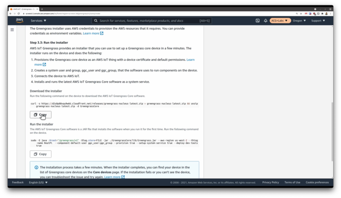
After you execute the two Copy/Paste commands, you should see RealPi show up on the Greengrass IoT console. Next, I'm going to send down the JVM config update by itself. You can consult Part 1 for how to customize the aws.greengrass.Nucleus component. While our memory update rolls out, While we're waiting for Greengrass to do all its stuff, let's add the ggc_user account to the video group so it can access the camera device. I also want to add this user to the GPIO group as I'll have a temperature and humidity sensor which uses the GPIO pins.
$ sudo usermod -a -G video,gpio ggc_user
Do be sure that you give greengrass plenty of time to finish its deploy especially on the relatively slow Pi Zero. You can keep tabs on it by watching the logs or watching the processes using top. Once everything is settled, we can reboot the Pi to make sure the new JVM parameters are applied.
$ sudo cat /greengrass/v2/config/effectiveConfig.yaml
snapPicture Component
Let's go back to our IoT console and create our snapPicture component. Same method as we used for our first component in Part 1. One thing I discovered is that apparently your artifacts must be contained within a bucket in the same region as Greengrass so keep this in mind if you're using different regions.
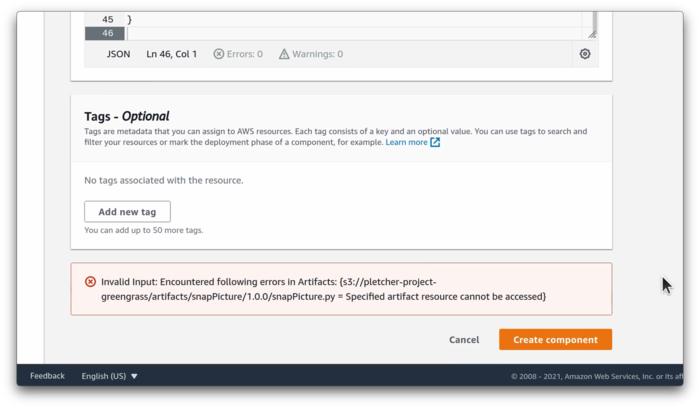
You'll see that in our snapPicture-1.0.0.json recipe Manifest section, we're adding in the PiCamera python library and an Adafruit library for our DHT sensor. When this component is deployed to the device for the first time, the pip3 command will pull down and install all the components. Now, downloading and installing all those components for the first time takes a while and I have noticed sometimes the greengrass deployment process times out waiting for all the components to install. I'm sure we could adjust the timeout but we're going to help it along by pre-installing those components, but we must install them under the greengrass runtime user account. So now, with the first deployment of our component, pip3 will notice that we have already satisfied the dependencies and shuffle on along.
$ sudo su ggc_user
$ pip3 install --user awsiotsdk boto3 picamera Adafruit-DHT
Now, just a word of caution here...if you still have your FakePi instance running and receiving this update, the deployment will fail on that system because picamera won't install on a non-Raspberry Pi device so the pip3 install command will error out and thus make Greengrass report that the installation failed. You can ignore this or remove that device from the group if you'd like.
Testing Time
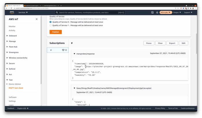
Once deployed, we can again go to our MQTT test bench and send a message on the picam/request topic. If we're living right, we'll get back a JSON response with a URL to the image that was captured. Do keep in mind that the little Pi Zero isn't very powerful and in my case, it was taking up to a good 10 seconds or so before I got the response.
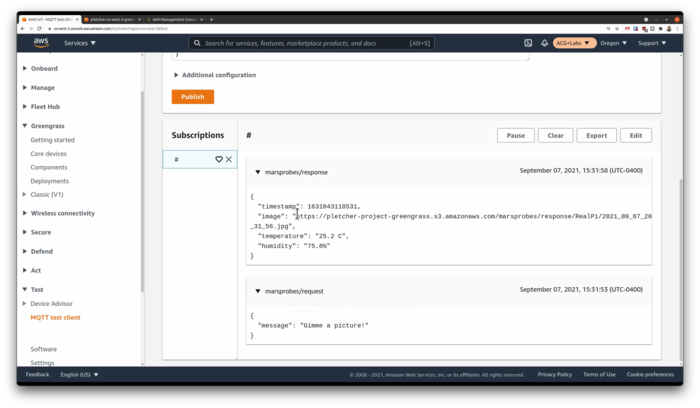
Of course, this delay would be greater if I had the Pi configured to only connect to the internet every 10 minutes for example but that's the benefit of the MQTT message queueing approach...it's designed for those types of intermittent connections. In the MQTT test console, I can set attributes for the message and I can keep it in the queue until the device comes back online. We can demonstrate this by shutting down the greengrass process on the pi...
$ sudo systemctl stop greengrass
Then creating our message with the Retain Message flag selected. Then, when we start back up the greengrass process, it will see the new message and act upon it. As greengrass comes back up, it sends back some status information on the MQTT queue that you'll see here.
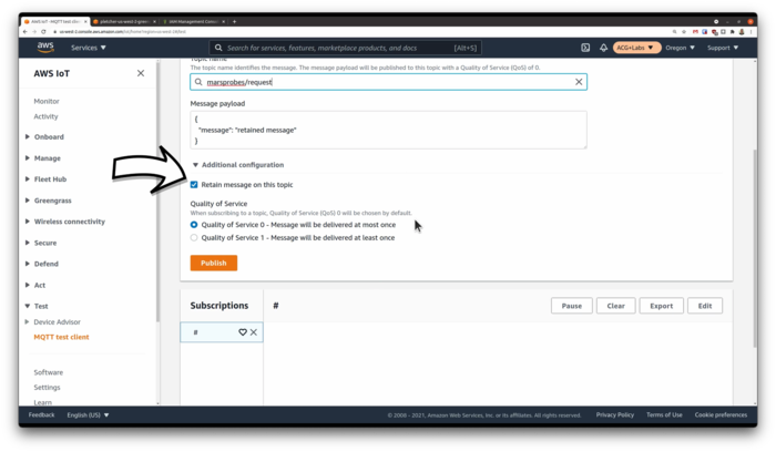
Once our snapPicture process is up and running again, we should see a response come through. Additionally, the Core Devices can also act as a local proxy for MQTT messages for other local devices and this is really useful for those sensors that don't have the capability or capacity to store or queue data locally.
You can have some more fun with MQTT and GreenGrass by using a tool like Node-RED to build some simulations if you'd like, but the rest of this video will focus on building out the hardware components of our Mars Probe.
Hardware Solution
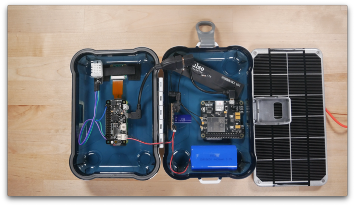
This physical build consists of a few basic components. All in, everything was under $100 US but I had most of this stuff already laying around. We start with the brains...the Raspberry Pi Zero W. I customized this Pi slightly by soldering on the GPIO pinouts. I'm using a Sandisk ultra 32GB microSD card loaded up with Raspberry Pi OS Lite version. I'm also using a Pi Camera version 2.1 with the special Pi Zero connector ribbon.

For power, I have a UUGear Zero2Go Omini power controller. It's a neat little device that can accept three different power inputs and switch between them, regulating the voltage for the Pi. It also senses the incoming voltage and gracefully powers down the Pi when the voltage is too low and powers it back up when the voltage is at a sufficient level. And this is perfect for a solar powered application. I also have an Adafruit solar change controller which can power the pi and charge the battery when the sun is out and switch over to the battery when there isn't any sun. I customized this component by adding a 4700 micro-farad capacitor, which acts as a sort of electron buffer and allows for a smoother transition between power sources. Powering the rig is a 4400 mAh LiPo battery and a Voltaic 6 volt 3.4 watt solar panel. I also fabricate a little bracket for the solar panel from some scrap aluminum angle stock I had on hand.
Playing the part of the environmental sensor is a DHT22 temperature and humidity sensor connected to the GPIO pins zero and six for power and pin 26 for data. For our internet connectivity, I'm using a Sixafab Cellular IoT HAT with a Twilio Super SIM card. This SIM card is awesome in that it works pretty much anywhere in the world. For me located in the US, it provides access to the AT&T and T-Mobile data networks, depending on which has the strongest signal. Now, this modem can use the UART serial port if stacked on the GPIO pins, but I've found that the USB connection method had way better data performance. To use the USB cable for both data and power with this cellular hat, I did have to jumper two pads on the board itself.
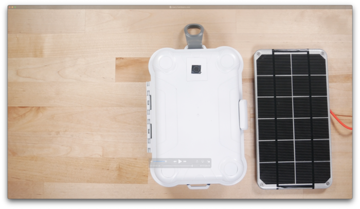
For the case, I picked up a cheap weatherproof case from my local big-box store for about $6 US. I spray painted it white and drilled two holes in it...one for the camera which I covered by glueing a thin piece of clear plastic over it. The other hole is for the solar panel connection...which I'm going to seal with silicone. On the inside, I used heavy duty 3M velcro to stick the components to the sides of the container. And that is my self-contained mars probe!
What Did I Learn?
So, what were some lessons for me on this project? Well, I learned that there were a decent number of resources out there for Greengrass version 1 but not much at all around version 2. Hopefully, this project will help fill in some of that empty space. I also learned that with version 2, AWS seems to be deemphasizing the use of Lambda functions with Greengrass and this doesn't hurt my feelings at all. With version 1, I often found using Lambda was kind of an extra layer of complexity that didn't really seem necessary. And there are still some rough edges in the user interface and overall experience. The greengrass cli is limited and not intuitive at all. It doesn't seem like we can delete old deployments and I had phantom components still associated to core devices I had long since deleted and re-provisioned. For someone who likes to keep a meticulously clean console, these little leave-behinds really bug me.
Overall, this project was a pretty steep learning curve for me. I ran into many roadblocks and dead-ends...I wasn't sure if I was doing something wrong, maybe I was running into platform bugs or maybe I was using outdated documentation or examples. But, that's the learning process...we have to keep trying different things until we land on something that seems to work. So, I certainly don't consider this project to represent a reference architecture for a major production IoT deployment but maybe it helps spark interest in the topic for someone somewhere. What's next? How about a Mars Rover?
If you'd like to watch a video version of this complete tutorial, do head on over to A Cloud Guru's ACG Projects page. There, you will find this a other hands-on tutorials designed to help you create something and learn something at the same time. Accessing the videos does require a free account, but with that free account, you'll also get select free courses each month and other nice perks....for FREE!
