Article Series
Introduction
This article is Part II of a series of articles attempting to introduce the reader to the world of embedded systems and their applications in the industry. In this article we will concentrate more on the BASIC Stamp II microcontroller and how it will be used in our robotics project. If you have not read Robotics/Embedded Systems Part I please take some time to read it to get an insight into the possibilities of robotics and embedded systems.
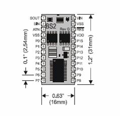
The figure above, illustrates the BASIC Stamp II microcontroller. In the following sections we will get into the details of the microcontroller and get an overview of its architecture, the Input and Output (I/O) pins present, and the instruction set for the microcontroller.
Background/Reference
Understanding of computer architecture and microcontrollers is a plus for this series of articles. I will be discussing system design and theoretical concepts of microprocessor. Also some basic electronics knowledge would be helpful once we get into circuit design for the robot.
Brief History of the BASIC Stamp Microcontroller
BASIC Stamp microcontrollers have been in use by engineers since they were introduced in 1992. Since their introduction, the BASIC Stamp line of microcontrollers has evolved into six models and many physical package types. We will be using the BASIC Stamp 2e microcontroller for constructing and controlling our robot.
The following table lists the model comparison for the BASIC Stamp II microcontrollers. Of course since the architecture of some of the more advanced microcontrollers are different, the instruction set is also different and handled differently internally.
Microcontroller
| Description |
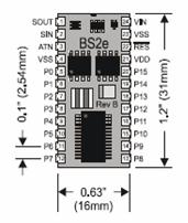
BASIC Stamp 2e
|
- Firmware: 1.1
- Microchip: Ubicom SX28AC
- Processor Speed: 20MHz
- Program Execution Speed: ~4,000 instructions/second
- RAM Size: 32 Bytes (6 I/O, 26 Variable)
- EEPROM Program Size: 8 x 2K Bytes, ~4,000 instructions
- Voltage Requirement: 5-12 vdc
- Current Draw @ 5v: 25mA Run, 200µA Sleep
- PBASIC Commands: 45
|
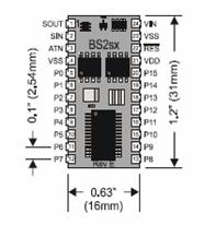
BASIC Stamp 2sx
|
- Firmware: 1.1
- Microchip: Ubicom SX28AC
- Processor Speed: 50MHz
- Program Execution Speed: ~ 10,000 instructions/second
- RAM Size: 32 Bytes (6 I/O, 26 Variable)
- EEPROM Program Size: 8 x 2K Bytes, ~4,000 instructions
- Voltage Requirement: 5-12 vdc
- Current Draw @ 5v: 60mA Run, 500µA Sleep
- PBASIC Commands: 45
|

BASIC Stamp 2p
|
- Firmware: 1.4
- Microchip: Ubicom SX48AC
- Processor Speed: 20MHz Turbo
- Program Execution Speed: ~12,000 instructions/second
- RAM Size: 38 Bytes (12 I/O, 26 Variable)
- EEPROM Program Size: 8 x 2K Bytes, ~4,000 instructions
- Voltage Requirement: 5-12 vdc
- Current Draw @ 5v: 40mA Run, 350µA Sleep
- PBASIC Commands: 61
|
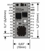
BASIC Stamp 2pe
|
- Firmware: 1.1
- Microchip: Ubicom SX48AC
- Processor Speed: 8MHz Turbo
- Program Execution Speed: ~6,000 instructions/second
- RAM Size: 38 Bytes (12 I/O, 26 Variable)
- EEPROM Program Size: 16 x 2K Bytes (16K for source)
- Voltage Requirement: 5-12 vdc
- Current Draw @ 5v: 15mA Run, 150µA Sleep
- PBASIC Commands: 61
|
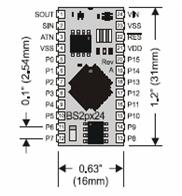
BASIC Stamp 2px
|
- Firmware: 1.0
- Microchip: Ubicom SX48AC
- Processor Speed: 32MHz Turbo
- Program Execution Speed: ~19,000 instructions/second
- RAM Size: 38 Bytes (12 I/O, 26 Variable)
- EEPROM Program Size: 8 x 2K Bytes, ~ 4,000 instructions
- Voltage Requirements: 5-12 vdc
- Current Draw @ 5v: 55mA Run, 450µA Sleep
- PBASIC Commands: 63
|
We will be using BASIC Stamp 2e as the brains for our robot.
Features of the BASIC Stamp Microcontrollers
BASIC Stamp II microcontrollers are designed for use in a wide array of applications. Many projects that require an embedded system with some level of intelligence can use the BASIC Stamp modules as the controller. Each BASIC Stamp microcontroller comes with a BASIC Interpreter chip, internal memory (RAM and EEPROM), a 5-volt regulator, a number of general purpose I/O pins (TTL-level, 0-5 volts), and a set of build in commands for math and I/O pin operations. They are capable of running a few thousand instructions per second and are programmed with a simplified, but customized form of the BASIC programming language, called PBASIC. We will cover some of the PBASIC commands in this article. More will be covered as we start building the robot.
BASIC Stamp II Architecture - Memory Organization
The BASIC Stamp II microcontroller has two kinds of memory, RAM (for variables used by the program) and EEPROM (for storing the program itself). EEPROM may also be used to store long term data.
The BASIC Stamp II model has 32 bytes of Variable RAM space. The first six bytes are reserved for input, output, and direction control of the I/O pins. The remaining 26 bytes are available for general purpose use as variables. It has an extra INS, OUTS and DIRS registers for a total of 38 bytes of variable RAM. These are shadow registers that are switched in and out of the memory map with the AUXIO, MAINIO, and IOTERM commands. The following table will show the arrangement of the RAM space:
WORD Name
| BYTE Names
| NIBBLE Names
| BIT Names
| Special Notes
|
INS
| INL, INH
| INA, INB, INC, IND
| IN0-IN7, IN8-IN15
| Input pins
|
OUTS
| OUTL, OUTH
| OUTA, OUTB, OUTC, OUTD
| OUT0-OUT7, OUT8-OUT15
| Output pins
|
DIRS
| DIRL, DIRH
| DIRA, DIRB, DIRC, DIRD
| DIR0-DIR7, DIR8-DIR15
| I/O pin direction control
|
W0
| B0, B1
| | | |
W1
| B2, B3
| | | |
W2
| B4, B5
| | | |
W3
| B6, B7
| | | |
W4
| B8, B9
| | | |
W5
| B10, B11
| | | |
W6
| B12, B13
| | | |
W7
| B14, B15
| | | |
W8
| B16, B17
| | | |
W9
| B18, B19
| | | |
W10
| B20, B21
| | | |
W11
| B22, B23
| | | |
W12
| B24, B25
| | | |
The word variable INS is unique in that it is read only. The 16 bits of INS reflect the state of I/O pins P0 through P15. It may only be read, not written. OUTS contain the states of the 16 output latches. DIRS controls the direction (input or output) of each of the 16 I/O pins.
A 0 in a particular DIRS bit makes the corresponding pin in an input and a 1 makes the corresponding pin an output. For example, if bit 5 of DIRS is 0 and bit 6 is 1, then I/O pin 5 is an input and I/O pin 6 is an output. A pin that is an input can e controlled by circuitry outside the BASIC Stamp II microcontroller, and the microcontroller cannot change its state. A pin that is an output is set to the state indicated by the corresponding bit of the OUTS register.
When the BASIC Stamp II is powered up, or reset, all memory locations are cleared to 0, so all pins are inputs (DIRS = %0000000000000000). Also, if the PBASIC program sets all the I/O pins to outputs (DIRS = %1111111111111111), then they will initially output low, since the output latch (OUTS) is cleared to all zeros upon power up or reset.
In summary, DIRS determines whether a pin's state is set by external (input, 0 ) or by the state of OUTS (output, 1). INS always matches the actual state of the I/O pins, whether they are inputs or outputs. OUTS holds bits that will only appear on pins whose DIRS bits are set to output.
As stated previously, the BASIC Stamp II module's memory is organized into 16 word of 16 bits each. The first three words are used for I/O. The remaining 13 words are available for use as general purpose variables.
Defining Variables for BASIC Stamp II Microcontrollers with PBASIC
Before using variable(s) in a PBASIC program, they must be declared. The following is a sample of how to declare a variable for BASIC Stamp II microcontroller:
name VAR Size
where name is the identifier of the variable and Size indicates the number of bits of storage for the variable.
For the BASIC Stamp II microcontroller, the Size argument has four different choices:
Bit (1 bit)
Nib (nibble, 4 bits)
Byte (8 bits)
Word (16 bits)
Example of variable declarations:
Sample Declaration
| Range
|
myBit VAR BIT
| Value can be 0 or 1
|
myNib VAR NIB
| Value can be 0 to 15
|
myByte VAR BYTE
| Value can be 0 to 255
|
myWord VAR WORD
| Value can be 0 to 65535
|
You can also define multipart variables called arrays. An array is a group of variables of the same size, and sharing a single identifier (variable name), but broken up into numbered cells, called elements. The syntax for defining an array in PBASIC is:
name VAR Size(n)
where Size(n) tells PBASIC how many elements the array to have. For example: myArray VAR BYTE(10) will create a 10-byte array. Another unique property of PBASIC is that you can refer to the 0th cell of the array by using just the array's name without an index value.
You can also use what is called an alias as an alternative name for an existing variable. For example:
myVar VAR BYTE
myAlias VAR myVar
This means that both names refer to the same physical memory location. The alias can also serve as a window into a portion of another variable. This can be done by the use of modifiers. For example:
myWord VAR WORD
highByte VAR myWord.HIGHBYTE
lowByte VAR myWord.LOWBYTE
where HIGHBYTE will represent the highest 8 bits and LOWBYTE will represent the lowest 8 bits. So if the value of myWord is 0001110111110000 then the HIGHBYTE will contain 00011101 and LOWBYTE will contain 11110000.
The BASIC Stamp II microcontroller also has an additional RAM called Scratch Pad RAM. The size is 64 bytes. The Scratch Pad RAM can only be accessed with the GET and PUT commands and cannot have variable names assigned to them. The highest locations in SPRAM (location 63) is special-purpose, read-only location that always contains special run time information. The following is a table of the SPRAM:
Location
| BS2
|
0 to 62
| General Purpose RAM
|
63
| Bits 0-3: Active program slot number.
|
We will cover more of the instruction for the BASIC Stamp II in the next article.
Points of Interest
In the last few years, there have been much interest and enthusiasm in the fields of robotics. This is due to the availability of cheaper and more advanced microcontrollers. There is however one more frontier which needs to be addressed before we can see more interesting and sophisticated application introduced into the market place. And that is having standards for the industry. I see Microsoft's announcement of their Robotics Studio as a step forward in this direction, and from the looks of it, the industry has welcomed the initiation warmly! This will lead to the same phenomenon which happened to the personal computer in the early days with the introduction of the IBM PC. I feel that in the next few years and specifically in the next decade there will be great achievements in the robotics field, and maybe we can realize some of the dreams we have had growing up come true. Walking, talking, and thinking robots that can benefit humanity in many aspects.
