Get access to the new Intel® IoT Developer Kit, a complete hardware and software solution that allows developers to create exciting new solutions with the Intel® Galileo and Intel® Edison boards. Visit the Intel® Developer Zone for IoT.
The example app in this guide rotates a servo motor connected to your Intel® Edison board when you turn the knob on a rotary angle sensor. This is a simple Node.js* application created using the Grove* - Starter Kit: Intel IoT Edition. The sample code can be found in the following location: https://github.com/gomobile/iotapp-servrotary
- The Grove* - Servo motor is a fun motion control device that can be located at any position between 0 to 180 degrees. With 4 shafts in different shapes, this servo is ready to drive a small fan, lift an object, or mimic a clock hand.
- The Grove* - Rotary Angle Sensor is a 10k ohm linear rotary potentiometer. It has an active range of 300 degrees. It is also designed as a HID device and includes a "panel mount"feature.
videos/servrotary
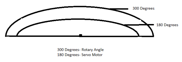
The knob on the rotary angle sensor turns more dramatically than the servo due to its greater range of motion: 300 degrees, compared to the 180 degrees available to the servo motor. But presumably, you want to have the servo turn for the rotary angle sensor's full range of motion -- not just have the servo stop when the knob on the rotary angle sensor reaches 180 degrees.
For this reason, the app code needs to perform some one-on-one mapping. This ensures that when you turn the knob all the way to its maximum position, 300 degrees, the servo will also be at its maximum extended position.
After getting the absolute raw knob value in radians from the AIO pin attached to the rotary angle sensor, the app code sets the servo angle to the mapping ratio, as follows:
Mapping ratio = (Servorange/ Knobrange) * Knobvalue
In this case:
- Servorange = 180 degrees
- Knobrange = 300 degrees
- Knobvalue is retrieved from the function
groveRotary.abs_deg().

Requirements
Assembling your board and Grove kit components
This section contains steps to connect your board to the servo and rotary angle sensor.
- Line up the male header pins on the bottom of your base shield with the female pins on the expansion board, as shown in the image below. Once aligned, gently push the base shield down firmly and evenly towards your board until it is securely attached.

- Check that the voltage toggle switch (which is marked VCC and located next to the A0 socket) on the base shield is set to 5V.
- Slide the other end of the servo cable into the D5 socket on your base shield until you feel the cable snap into place.

- Slide the connector on one end of the Grove - cable into the socket on your rotary angle sensor until you feel the cable snap into place.

- Slide the other end of the cable into the A0 socket on your base shield until you feel the cable snap into place. An example of the completed setup is shown below.

References
