Introduction
Many modeling standards such as UML take a generalized approach to their standard. During implementation and/or maintenance, this can cause uncertainty with the practical relationships between components - specifically with class diagrams. This article attempts to take the ubiquitous symbols common with class diagramming and redefine them towards more implementation-oriented relationships. Whether the benefits of such an approach are useful, I leave to you.
Background
The most common modeling language in my experience is UML. Whether you know that name or not, you've probably seen class diagrams loosely based on UML. Let's have a refresher on the basic class relationships in UML.

In the following descriptions, 'A' refers to the base object while 'B' refers to the object pointed to by 'A'.
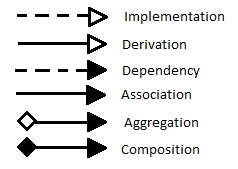
Implementation and derivation are both class-definition relationships. Implementation models relationships like a class and an interface where B is implemented by A. Derivation or inheritance models relationships where B is inherited by A. These two are pretty self-explanatory.
Class-instance relationships are modeled using dependency, association, aggregation, and composition. Dependency indicates that A uses B but holds no reference or the reference is trivial (e.g. only used for object creation). Association is when a reference is held and the object is intended to be used. Aggregation is an odd relationship. It models the whole-part "has a" relationship but is considered to have no defined practical meaning since adding multiplicity to an association accomplishes the same thing. Composition is an aggregation that also implies lifecycle control kind of like an "owns a" relationship.
The Problem
The standard class-instance relationships are pretty good for modeling referential relationships but one problem is references aren't the only property of class-instance relationships. Consider the following definition of the Factory Method pattern:

Creator uses the FactoryMethod() inside Operation() to create a Product. This is the problem. Without a footnote, explanation, or specific naming convention on the diagram, it wouldn't be obvious that the dependency between ConcreteCreator and ConcreteProduct is a creational relationship. This aspect of class interaction isn't being modeled. In a simple example like this with a well-known pattern, a quick footnote would be fine. But what about a large project that includes a dependency injection framework which manages some classes but not others? That could get ugly with footnotes real fast.
Another problem is that the standard symbols aren't succinctly fine-grained. What would you do if there's a lifecycle control requirement but no whole-part relationship between classes? Add 1-to-1 multiplicity onto the composition? That feels like putting a band-aid on a much bigger problem.
Analysis
So what we need is a way to model the referential and creational relationships ideally using only the existing symbols. The following table represents the combinations we'd like to model.
| Create | Reference | Lifecycle Control |
| N | N | N |
| N | Y | N |
| N | Y | Y |
| Y | N | N |
| Y | Y | N |
| Y | Y | Y |
Note: YNY and NNY have been omitted as you can't have lifecycle control without a reference.
The table shows creation is an independent binary relation - you create or you don't. Reference and lifecycle control are a coupled ternary relation - no reference + no LCC, reference + no LCC, and reference + LCC. Together, they make up six distinct relationships.
Looking back at the standard symbols, the arrow already has a useful meaning - whether the relation is a definition or instance relationship. That leaves us the line and the diamond. The line is a binary symbol; it can be either solid or dashed. The diamond is a ternary symbol; it can either not exist, not be filled, or be filled.
Proposed Solution
Conveniently, this means the creational relationship can be defined by the line while the referential relationship is defined by the diamond. Keeping as close as possible to the traditional meaning of the symbols, my proposed relationship modeling system is:

In the Factory Method example earlier, it no longer becomes necessary to specify a footnote about creation - simply use a solid line. Here's an example of the more complex Abstract Factory pattern:

Without footnotes, the standard diagram is much less expressive. Only the referential coupling is specified. The proposed diagram expresses multiple implementation details right off the bat. The factory and product relationship is purely a creational relationship. The client controls the lifecycle of factory instances and holds references to the products but does not create them. This immediately makes the pattern obvious. The factory creates products; the client uses them.
Final Thoughts
In this new system, the class relationships are no longer constrained by generalized concepts like dependency or aggregation. All relationships are well-defined. Additionally, since the creational and referential relationships are independent, symbols become tiered and the overall relationship is constructed from these symbols.

These properties make it easier to adjust the relationships. In the previous abstract factory example, it would be awkward to move from a client-product association to a client-product composition if lifecycle control became a requirement due to the whole-part and creational assumptions that come with compositions. The new system simply requires changing the hollow diamond to a filled diamond. In my opinion, this makes diagrams meant to document an implementation much more flexible, easier to maintain, and easier to understand.
History
- 3/1/2018: Initial release
