Introduction
This article describes a way of implementing a SmartCard control based application upon a Serial interface.
The hardware interface used is widely known as "Phoenix", and I'm going to describe the hardware architecture about this, and how to integrate it with a Visual Basic application needless to use PC/SC specification.
Otherwise, the target of this article is to show how to directly interact with the smartcard toward the hardware interface told before.
Each SmartCard vendor implements its own command set named APDU (Append Protocol Data Unit) based on ISO-7816 specification. In this way, we can explode each SmartCard type with the correct APDU commands set; in this way, we can use Mifare, TIBC or any other type of Smartcard as an RFID Tag for identity purposes by this VB interface.
To get it working, it's only necessary to feed the circuit with 5V continuous current and an RS-232 PC serial interface.
Interface
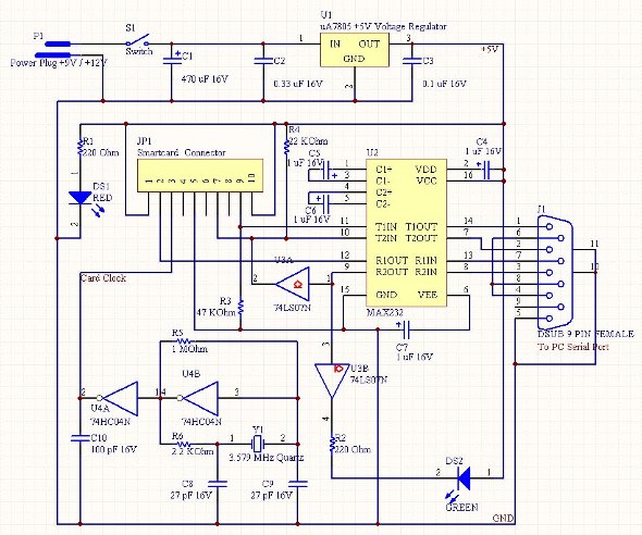
Phoenix interface is a serial interface with a 9 pin serial jack, and a 10 pin SmartCard connector (pins 4, 6 and 8 unplugged). This interface is just developed and it's the base of this project.
It's composed of a 10 pin SmartCard module, a MAX232 IC used to convert RS-232 (serial) levels to TTL voltages, a 3.579 Mhz quartz crystal used as pulse generator, a voltage regulator and several capacitors, resistors and leds used as pull-up/pull-down resistors, or voltage generators basically.
The serial port pin connections are shown in phoenix electronic schema:

The idea is to connect the Tx and Rx serial pins with the SmartCard interface I/O pin managed by a bidirectional logic.
Otherwise, SmartCard reset pin is connected via MAX232 to RTS serial line, so reading the ATR is so easy as driving this line to inverse voltage levels during a few clock cycles.
SmartCard connector pinout is shown in this table:
Smartcard Module PinOut
| Pin # | Pin Name | Pin Description |
|---|
| 1 | VCC | +5v or 3.3v DC |
| 2 | Reset | Card Reset |
| 3 | CLOCK | Card Clock |
| 5 | GND | Ground |
| 7 | I/O | In/Out [Data] |
| 9,10 | AS | Presence Switch |
Using the Code
The program resident on host machine is responsible for the serial port initialization and reading/writing process. Getting finite states machine ready to accept commands, here is the sequence:
Once the serial port is initialized, getting the interface ready for reading/writing is composed of only 4 steps:
- Feeding the SmartCard; this is got by connecting RS-232 interface and Vcc SmartCard pin will be directly fed by Vcc Serial pin.
- Initializing serial communications; this interface needs to be initialized to 9600 bauds, equal parity, 8 data bits and 1 parity bit:

- Reseting the SmartCard; you can do it by putting tension on serial 4 pin and then putting it off. After about 40000 cycles (depends on card), you can read the ATR at serial buffer register; so, 100 msg is enough time.
ObjSerial.RTSEnable = True
ObjSerial.RTSEnable = False
Sleep (100)
buffer$ = ObjSerial.Input
Translating ATR byte[] to strings of pairs is done by InterpretarHex function:
Private Function InterpretarHex(buffer, Optional conEspacios As Boolean) As String

	Dim sol As String
	Dim byteAux

	If Len(buffer) > 0 Then
		byteAux = Hex(Int(Asc(Mid(buffer, 1, 1))))
		sol = byteAux
		For i = 2 To Len(buffer)
			byteAux = Hex(Int(Asc(Mid(buffer, i, 1))))
			If Len(byteAux) = 1 Then byteAux = "0" + byteAux
			If (conEspacios) Then
				sol = sol + " " + byteAux
			Else
				sol = sol + byteAux
			End If
		Next i
	End If

	InterpretarHex = sol

End Function
- Reading serial buffer gets the Answer To Reset bytes (ATR).
buffer$ = ObjSerial.Input

Once having read serial buffer and having RTS pin at low level, the interface is ready for the transmission of the desired APDU command.
Here's an APDU example :
ObjSerial.RTSEnable = False

For i = 1 To (Len(txtCmd.Text) / 2)
    ObjSerial.Output = Chr(Comanda(Mid$(txtCmd.Text, i, 2)))
Next i

buffer$ = ObjSerial.Input
txtResponse.Text = InterpretarHex(buffer$)

This is a picture of the working project:

Points of Interest
This software/hardware interface could be used to integrate SmartCard login in any application you could think about, or you can use it for SmartCard investigation projects.
History
- 1st November, 2010: Initial version
