Introduction
I purchased one of the many 4WD chassis robots that can be found on the internet at a low price. There are all the basic components to allow your robot to navigate. I would like the robot to move independently, to avoid obstacles, to move freely around the room. I realized that I have 4 DC TT gearbox motors fixed in the chassis without any possibility of steering. How can I rotate 90 degrees, or 180 degrees, or 360 degrees without a wheel encoder or compass or gyro sensor?

Components
1 4WD robot kit
if not present:
1 Arduino nano v 3.0 or Arduino Uno
2 L298N
1 220 K potentiometer
4 TT gearbox motors
2 18650 battery 3.7 V (7.4 V)
1 power switch
The Theory
Reading the motors specifications I tried to reach some useful informations.

These calculations are true if:
- Vcc is constant
- The motor is not subjected to any load (wheel, weight, traction, etc,)
So, for example, with a Vcc=4.5V, to turn 1 degree my robot I'll have to give power to the motor for 0.9 msec at max speed.
A note: L298N makes a voltage drop of about 2V. So our 7.4 V will drop to 5.4 V to the motors (I tested about 5.3 V).
So with Vcc=5.3V the calculations would be:


Note: The ratio between Vcc and RPM seems to be linear.
The Practice
If we want to go deep, we would consider a lot of further variable to add, one is the weight of all the robot components that alter the motion, the traction, the total inertia, other, the shape of the chassis.
We are lucky to have an almost square shape but take in mind that decreasing the wheelbase (distance between the front and rear set of wheels), results in better zero-radius turning in any direction with 4 wheel drive robot and better efficienty in rotating in pivot position. Next time I will buy a Tank like chassis. Here you can find a really good explanation about the shapes.
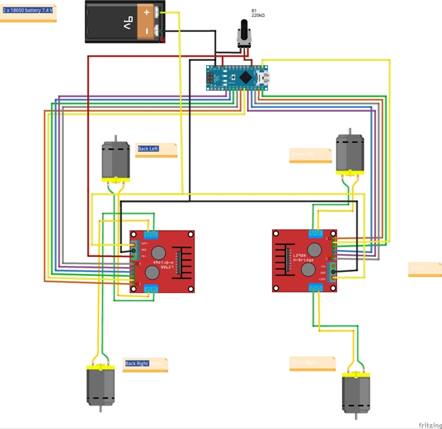
Now that we have all the components connected. Give a deep look to the connections. A good trick is to see them again from another point of view. Another trick is to check and test electrical circuit connections block by block. A tester is welcome.

The Code
The Arduino sketch contains all the commands to make your robot move in all directions. My intent is to make sure that these commands are working correctly to be recalled in an IoT environment, integrating the robot with a GPS and other sensors, a camera and .... the best is yet to come!
I will concentrate my explanations to reach an in-place 90, 180, 360 degree turning.
This block to define the motors:
#define ENA_F_FL 10 // Enable/speed motor Front Left D10->ENA L298N Front Side
#define IN_F_FL_1 8 // L298N #2 in 1 motor Front Left D8->IN1 L298N Front Side
#define IN_F_FL_2 9 // L298N #2 in 2 motor Front Left D9->IN2 L298N Front Side
#define ENB_F_FR 11 // Enable/speed motor Front Right D11->ENB L298N Front Side
#define IN_F_FR_3 12 // L298N #2 in 3 motor Front Right D12->IN3 L298N Front Side
#define IN_F_FR_4 13 // L298N #2 in 4 motor Front Right D13->IN4 L298N Front Side
#define ENA_B_BL 5 // Enable/speed motor Back Left D5->ENA L298N Back Side
#define IN_B_BL_1 2 // L298N #1 in 1 motor Back Left D2->IN1 L298N Back Side
#define IN_B_BL_2 3 // L298N #1 in 2 motor Back Left D3->IN2 L298N Back Side
#define ENB_B_BR 6 // Enable/speed motor Back Right D6->ENB L298N Back Side
#define IN_B_BR_3 4 // L298N #1 in 3 motor Back Right D4->IN3 L298N Back Side
#define IN_B_BR_4 7 // L298N #1 in 4 motor Back Right D7->IN4 L298N Back Side
The potentiometer regulates the motor speed, and we calculate that value in speedCar:
int speedCar = 0; int speed_Coeff = 4; int potValue = 0;
Next constant value is the key value to determine how many msecs the motors have to be powered on to turn predefined degree:
const float timeFact = 0.78;
I started with the theorical ideal value timeFact = 0.78 (approximated value got from the table "The theory").
The functions turnLeft and turnRight are working identically. Therefore I will explain turnLeft:
void turnLeft(int degree = -1)
The parameter degree is optional, if I don't provide it, the value -1 will be passed and the function will behave as a standard turnLeft function. Providing a 90 value I will aspect an in-place turn left of 90-degrees and so on.
As I thought, I would not have expected a 90-degrees turn, but not even a bad 10-degrees!
This function take advantage of differential steering arrangement, where to turn left, the two wheels on each adjacent side (left and right ) must rotate on opposite spin at same speed:
void turnLeft(int degree = -1)
{

  digitalWrite(IN_F_FL_1, LOW);
  digitalWrite(IN_F_FL_2, HIGH);
  analogWrite(ENA_F_FL, speedCar);

  digitalWrite(IN_F_FR_3, HIGH);
  digitalWrite(IN_F_FR_4, LOW);
  analogWrite(ENB_F_FR, speedCar);

  digitalWrite(IN_B_BL_1, LOW);
  digitalWrite(IN_B_BL_2, HIGH);
  analogWrite(ENA_B_BL, speedCar);

  digitalWrite(IN_B_BR_3, HIGH);
  digitalWrite(IN_B_BR_4, LOW);
  analogWrite(ENB_B_BR, speedCar);

  if (degree > -1)
  {
    delay(timeFact * degree);
    stopRobot();
  }
}
Now, instead of 90 degrees, the robot turned left about 9 degrees.
Download robot_9_degree.mp4
May be it is keeping the same linear ratio found before (between Vcc and RPM) so:
If using the timeFact = 0.78 I got 9 degrees, to do a 90 degrees turning, do I will have to use timeFact = 7.8 ?
Let's try!
Download robot_90_degree.mp4
Here we are! It is working!
We reached our goal! We can send to our robot a turnLeft(90), turnLeft(180), turnRight(360) command with an acceptable approximation, without the need to buy specific sensors.
Installation
Download the Arduino sketch, unzip it and upload it to your Arduino.
History
2018-08-06 : First publication
