Introduction
In this post, I will be discussing how I got the stm32 discovery board working with the Keil IDE. This was my first time using an ARM processor, so I decided to go with a commercial grade IDE since they tend to be easier to use. As I switch over to GCC, I will document that process as well.
Background
For starters, you need the STM32 discovery board. Check it out at mouser.
Also, you will need the Keil IDE. You can download a free limited to 32KB program space version here.
Setting Up a Project
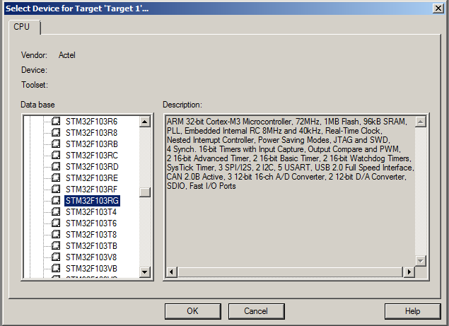
First off, you need to create a new project and select the processor in the ST Micro section:

It will then ask you if you want to Copy STM32 Start up Code to the Project Folder. Choose yes. I would then recommend you use the Keil STM32_init files. I found them in an example code. It can be found here. Once you have downloaded the files, unzip it. Copy over the following files to the same folder as the project file. STM32_Init.c STM32_Init.h STM32_Reg.h Now add STM32_Init.c to your project. Right click on the Source Group 1 and click add file to group. You can group them however you want, it doesn't change how anything builds.
Also, to keep things clean, we will create a Bin folder. So, we make a new directory in the same folder as our project. Next, right click on the Target folder and click options for target.

Then click output and click Select Folder for Objects and go find our bin folder that we created.

Finally, create and add a file (let's call it main.c). In there, add a main function that will call the Init code and include the init file. You might also want to include the STM32 lib file.
#include <stm32f10x_lib.h>
#include "STM32_Init.h"

int main (void)
{
   stm32_Init();
   return 0;
}
Now, we need to set up our debugging environment for the STM32 Discovery. First, we need to choose our debugger. So right click on the project and click options for target and head to the debug tab. Next, you don't want to be running a simulator so we will click the Use: radio button to the right half. In the drop down, we will choose the ST-Link Debugger. Then you need to click setting and choose SWD. Finally, I like to have run to main() check so that stops at the main before running.
 <stm32f10x_lib.h>
Next, we need to define the flashing tool to upload your program to the STM32. So head over to the Utilities tab and select the "Use Target Driver for Flash programming" radio button. Then, you can choose the ST-Link Debugger from the drop down.

Now you are all ready to debug.
Coding the Serial Port
This section we will setup the STM32 to echo what it receives on the serial port. The first step is to configure the usart. Open STM32_Init.c with the configuration wizard. I will write on how to do it in C when I cover getting started with GCC. Enable your USART1 and set the parameters. Also enable USAT1 interrupts on RXNE (receive) that way we don't need to poll the data and we will be notified when a byte has arrived.

Once every thing is configured to your liking, hit save. Now we will be able to use the structure called USART1. Here are a few notes on members that are used a lot.
USART1->SR this contains information about the interrupt that was generated USART1->DR. This contains the byte that we received or that will write if you assign USART1->DR a value, it will send that value out the usart. If you get the value form USART1->DR, if will read the value received from the usart.
Next, you need to open main.c. In this file, we will add the function definition for void USART1_IRQHandler (void). This function was declared STM32F10x.s and was all ready mapped to an interrupt vector. So all we need to do is enable the interrupt (which we all really did in the configuration wizard) and override it. My function will look a little bit like this:
void USART1_IRQHandler (void)
{
volatile unsigned int vsr;
int ByteSent;
vsr= USART1->SR;
if (vsr& USART_FLAG_RXNE) {
USART1->SR &= ~(USART_FLAG_RXNE);
ByteSent = (USART1->DR & 0x1FF);
SendByte(ByteSent);
}
}
We will of course need to define SendByte. The prototype will be void SendByte(int byte); My definition will look something like this:
void SendByte (int byte)
{
while (!(USART1->SR & USART_FLAG_TXE));
USART1->DR = (byte & 0xFF);
}
I also added an infinite loop right before the main returns. Now, you simply need to connect PA10 to RX and PA9 to TX on your hardware. I used the FTDI chip on my arduino to accomplish this. I simply connected PA10 to RX and PA9 to TX of my arduino and took the avr out. After that, whatever you send over to the terminal will echo back to you. If you need a terminal program, I used Termite.
Points of Interest
My code is BSD license, but I shipped the STM32_Init.c file that has its own license. But STM32_Init.c has its own terms of use.
History
- Jan 24 2011: Last updated
