Introduction
This brief article describes a frequency divider with VHDL along with the process to calculate the scaling factor.
The scaling factor
The frequency divider is a simple component whose objective is to reduce the input frequency. The component is implemented through the use
of the scaling factor and a counter. The scaling factor is the relation between the input frequency and the desired output frequency:

Assuming an input frequency of 50MHz and provided we need an output frequency of 200Hz, we yield:

Therefore, the counter of the frequency divider generates the output signal of 200Hz each 250000 cycles.
The code
Without any more delay, Listing 1 shows the source code for the frequency divider.
library IEEE;
use IEEE.STD_LOGIC_1164.ALL;
entity clk200Hz is
Port (
clk_in : in STD_LOGIC;
reset : in STD_LOGIC;
clk_out: out STD_LOGIC
);
end clk200Hz;
architecture Behavioral of clk200Hz is
signal temporal: STD_LOGIC;
signal counter : integer range 0 to 124999 := 0;
begin
frequency_divider: process (reset, clk_in) begin
if (reset =
temporal <=
counter <= 0;
elsif rising_edge(clk_in) then
if (counter = 124999) then
temporal <= NOT(temporal);
counter <= 0;
else
counter <= counter + 1;
end if;
end if;
end process;
clk_out <= temporal;
end Behavioral;
Lines 1 and 2 are equivalent to the C/C++ #include or the Python import statements. The inputs and outputs of the system are declared between the lines 4 through 10.
The frequency_divider process, lines 16 to 28, generates the 200Hz signal by using a counter from 1 to 124999. Why 124999 and not 250000? A clock signal is a square wave with a 50% of duty cycle (same time active and inactive); for this case, 125000 cycles active and 125000 cycles inactive. Since the counter begins at zero, the superior limit is 125000 - 1.
The reset signal is an essential part in any digital system and its function in this component is to restart the counter.
Simulating
In order to verify what I just said, a test bench is generated with the aid of the Xilinx ISE 13.1 software. Luckily, the software creates most of the test bench itself.
LIBRARY ieee;
USE ieee.std_logic_1164.ALL;
ENTITY clk200Hz_tb IS
END clk200Hz_tb;
ARCHITECTURE behavior OF clk200Hz_tb IS
COMPONENT clk200Hz
PORT(
clk_in : IN std_logic;
reset : IN std_logic;
clk_out: OUT std_logic
);
END COMPONENT;
-- Inputs
signal clk_in : std_logic :=
signal reset : std_logic :=
-- Outputs
signal clk_out : std_logic;
constant clk_in_t : time := 20 ns;
BEGIN
-- Instance of unit under test.
uut: clk200Hz PORT MAP (
clk_in => clk_in,
reset => reset,
clk_out => clk_out
);
-- Clock definition.
entrada_process :process
begin
clk_in <=
wait for clk_in_t / 2;
clk_in <=
wait for clk_in_t / 2;
end process;
-- Processing.
stimuli: process
begin
reset <=
wait for 100 ns;
reset <=
wait;
end process;
END;
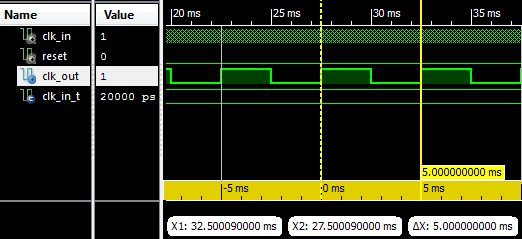
Finally, I show the result of the simulation:

