Introduction
nAML (.NET Application Modeling Language, pronounced as “namel”) is a visual modeling semantics to model .net applications with wide range of specific details. It contains extremely powerful visual notations and semantics to illustrate complex application components, processes and operations easily. It overcomes the limitation of traditional modeling languages by providing a single space to describe an application system with its structural and behavioral, as well as physical and logical components. One of it’s the most powerful objectives is nAML requires near to zero knowledge on notation semantics to understand an application system from readers perspective.
Example: Using nAML, for instance, a software architect can model a whole or part of a web application in a single visual diagram with respect to interaction, communication and structure between end user, web interface, .net classes, database objects, physical tiers (web server, business logic server, database server etc) and so on.
The primary objectives of nAML can be considered as follows:
- Provides a single space to visually describe one or more application systems with structural and behavioral components.
- Provides a single space to visually describe one or more application systems with logical and physical components.
- Provides a single space to visually describe one or more application systems from top to low level.
- Provides a single space to visually describe a part or whole of one or more application systems.
- Extremely simple and easy understand and learn from readers and designers perspective.
- Concentrates on .NET applications, with its related logical and physical entities (user interface, application logic, business logic, database etc).
Terms and Definitions
Element:
Definition
An Element is a structural notation that is the physical or logical object that holds one or more physical and/or logical objects.
Notation

Example
In an ASP.NET web application, an ASP.NET page can be an Element, having controls embedded within it as sub-Element and the event handler methods as defined Operation within it. For a .net class, the member Elements are the properties, data fields etc. For a physical database, its member Elements is the tables.
Operation:
Definition
An Operation is a behavioral notation that is the set of one or more actions to be performed that are defined in an Element.
Notation

or

Example
For instance, an ASP.NET page code behind class, as an Element, can have controls event handlers (click event handler of button etc) as Operation. For a .net class, the members Elements are the methods etc. For a physical database, its “Operation” can be defined within the stored procedure, functions.
Association:
Definition
Association is a structural notation that illustrates how the Elements or Operations are connected to other Elements or Operations.
Notation

Attribute:
Definition
Attribute is a structural notation that is the Meta data information that describes an Element, Operation or Association.
Notation
The notation of attribute can be simple text of an Element, Operation to be expressed as characteristics of another Element or Operation.
Example
For a .NET class “Employee” can have an Attribute as, Class Name: Employee
Element Lifeline:
Definition
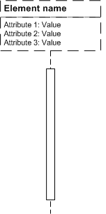
An Element lifeline is a behavioral notation which is the time span within which all activities related to the corresponding Element is illustrated. The life line also shows the active and inactive state of the Element. Each lifeline for a given Element applies to only one instance of that Element.
Notation

Example
If an instance of a .net class is being created, then its activation will be illustrated from the moment it created.
Common Semantic Guideline
- To distinguish structural and behavioral components of system, consider solid line diagrams as the behavioral component and dashed line diagrams as the structural component.
- Element Lifeline reflects the time span for behavioral components only, rather structural components
The Hello World! Sample
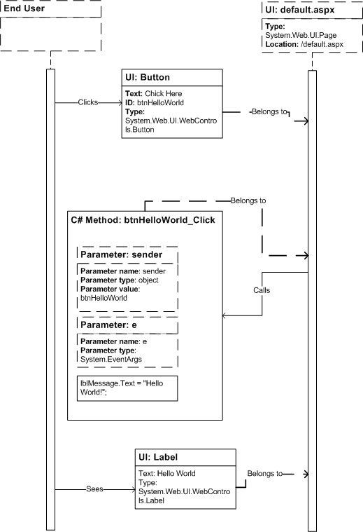
The sample illustrated below shows the “Hello World” message in an ASP.NET Label server control, when a user clicks on a ASP.NET Button server control.

Now let’s see the corresponding nAML notations implemented in this example.

Links and Downloads
Here is the nAML project site: http://code.msdn.microsoft.com/nAML
Download the latest specification, examples and Visio 2003 Stencil for nAML tutorial from here.
Download Visio 2003 Stencil for nAML from here.
History
Sep 12, 2008: Article posted, by Mohammad Ashraful Alam.
Sep 11, 2008: nAML v1.0 (Beta 1) released at code.msdn.microsoft.com, by Mohammad Ashraful Alam.
