Introduction
Raspberry Pi2 master and Pic24FJ64GB002 slave communicate over SPI.
I consulted the following links:
I used:
- VisualGDB to program Raspberry
- MPLAB X IDE v3.21 to program Pic
- pc: ASUS AMD X550ZE + Windows10
- developement board Microchip: Microstick II
Scheme 1
SLAVE (Pic24)                      MASTER (Raspberry)
Pin                                        Pin (GPIO)
 5        SDO1  ------------->   SPI0MISO      21
 4        SDI1   <-------------  SPI0MOSI      19
 6        SCk1  <--------------  SPI0SCLK      23
 7        SS1    <-------------    CS0         24

27        GND  ---------------     GND          9
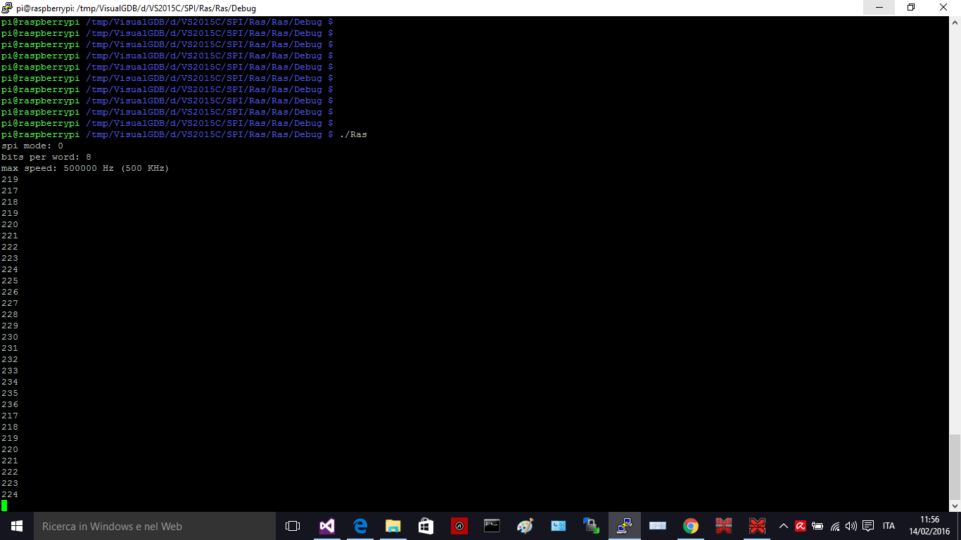
Load Ras in Raspberry, setting permissions. Load Sette HEX in Pic24FJ64GB002. Connect pins like scheme 1. Launch Ras.
Raspberry sends a number to Pic24 and Pick24 takes 17 from it and sends it back. Then Raspberry increments.
Load SpiWiring in Raspberry, setting permissions. Load Sette1 HEX in Pic24FJ64GB002. Connect pins like scheme 1. Launch SpiWiring.

This arrangement has 8 bit for Pic24 and for Raspberry: standard device with 8 bit default. I reach 200KHz.
Load PiGpioM in Raspberry, setting permissions. Load Sette2 HEX in Pic24FJ64GB002. Connect pins like scheme 1. Launch PiGpioM.
Raspberry sends a triplet to Pic24 and Pic sends back the triplet minus 15, then Raspberry increments the triplet by one. There is alignment to put better.
This arrangement has 16 bit for Pic24 and for Raspberry. Unfortunately, PiGpio doesn't have write or read functions to transfer 16 bit, but only 8 bit at a time. So I don't see the advantage of using auxiliary device for Raspberry. It's better the standard device with 8 bit default. Anyway, below is word mode. I reach 360KHz.
Load PiGpioM1 in Raspberry, setting permissions. Load Sette3 HEX in Pic24FJ64GB002. Connect pins like scheme 2. Launch PiGpioM1.
Raspberry sends a couple to Pic24 and Pic sends back the couple multiplied by 4, then Raspberry increments the couple by one.
Scheme 2
SLAVE (Pic24)                      MASTER (Raspberry)
     Pin                                                 Pin (GPIO)
      5        SDO1  ------------->   SPI0auxMISO          35
      4        SDI1   <-------------    SPI0auxMOSI        38
      6        SCk1  <--------------   SPI0auxSCLK         40
      7        SS1    <-------------    CS0aux             12

     27        GND  ---------------    GND                  9
PiGpioxxx projects want some include directives under VisualGDB:
Background
Enabling Raspberry's SPI with rasp-config; elementary knowledge of embedded microcontrollers.
Points of Interest
There are 3 approaches of Raspberry to Pic24: first is raw GNU code (1 byte); second and third custom libraries.

