Introduction
This tip is for beginners who want to explore AVR family of Micro controllers (MCUs) without buying actual hardware, or who want to simulate stuff before programming the code into flash. Let’s get started then…
What You Need
Download Atmel Studio 7. This IDE is free for download and just requires you to register. This is a Windows only software. Other OS fans, please excuse…
Follow the steps on how to install, it asks for few reboots that’s for installing few drivers…
I am following this example which explains how to work with external interrupts in Atmega8, but in that how to simulate without actual hardware is not given. In my tip, I will explain how to simulate external interrupts using Stimuli file. For a good understanding of this tip, please read the article given in this link. I changed a few lines to fit my requirement…
Brief Working
Simulators enable us to play around before actually using the hardware. In this tip, I am simulating external interrupt on Atmega8A MCU. I have enabled PIN2 (INT0) to receive interrupt, enabled global interrupt using sei(). ISR routine for INT0 is implemented where PIN6 is toggled. While debugging this code by executing the stimuli file, it writes to PIN2 so that interrupt is generated and ISR is called. Please see this link for a complete explanation.
Using the Code
Basically Stimuli file is something which when run from debug environment gives various inputs to simulated Micro controller. Stimuli file can have comments, delays, assignments and directives. Delay is how many CPU cycles it has to wait before executing the next statement, it starts with #. Assignments can be various inputs to PINs or PORTs. Directives are used to control execution and for logging, it starts with $. Paste this code into a text file with extension .stim file.
$repeat 2000000
PIND |= 0x04
#20
PIND = 0x0
#20
$endrep
Actual AVR C code...
#include <avr/io.h>
#include <avr/interrupt.h>
ISR (INT0_vect)
{
PORTD ^= (1 << PIND6); }
int main(void)
{
DDRD &= ~(1 << DDD2);
DDRD |= (1 << PIND6);
MCUCR |= (1 << ISC00); GICR |= (1 << INT0);
sei();
while(1)
{
}
}
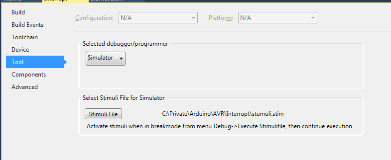
Under Project properties->Tools, you need to select the debugger as simulator and set the stimuli file...

Place debug break point at infinite while loop and choose execute stimuli from Debug->Execute Stimulifile. The Stimuli file starts toggling PIN2.

To observe what execution of Stimuli file is doing, open IO window, go to Debug->Windows->IO, Select I/O Port(PORTD). You will see PIN2 getting toggled repeatedly. This causes the interrupt to occur and call ISR function. If you keep debug breakpoint in ISR function, it will get repeatedly hit.

Points of Interest
Do select proper device when creating the project, the project files which I uploaded (Interrupt.zip) has Atmega8A as I am working with those MCUs. Do play around with other windows in Debug to explore more...
History
Please feel free to point out any mistakes, I will be glad to correct the same...
