Using a standard off the shelf module that can be reprogrammed and repurposed to suit an application with domestic and potentially larger scale applications.
Introduction
SCALAE WIFI Switch or SCALAE-IOT is a versatile modules that can be programmed to accomplish different tasks as needed. The hardware is arranged for a monitoring application with the ability to actuate autonomously and then provide reporting and feedback along with the option for remote control and monitoring.
This application will introduce the module's features and then step you through a basic application of measuring the analog value of a moisture sensor.
Background
While Arduino has been presented as the GOTO for many similar projects, this interpretation demonstrates how easily and simply this can be accomplished.
So that you have a better idea of what you are working with, here are the product's features.
| Specifications
| WiFi Switch
|
| Device
| PIC Microcontroller: PIC18F2xKxx - SOIC family device
|
| USB Connectivity
| YES - for system configuration local data logging.
|
| Device Programming
| ICSP | USART Bootloader
|
| Power Supply
| Onboard PSU, optimized for low-power operation.
|
| IO
| Reset Button, Opto Isolated inputs, Relay Output
|
| Temperature Sensors
| Dallas 1-Wire (Ruggardised), LM35*, DHT-11*
|
| Communication
| WIFI - ESP8266*, optional module
|
| USB UART
| CH340G
|
Using the code
The code has been written using MikroC , which is a C-centric compiler. The compiler is a very useful coding environment as it also includes many integrated libraries.
The code does the following:
-
Configure the hardware
-
Read the sensor
-
Process the reading
-
Report the value
#define AN1 1
char *ver ="Node_V_Dev";
char uart_rd;
char *SoilMoisValu ="0000";
char *SoilMoisTest="0000";
unsigned short ADC_channel;
unsigned temp;
int i;
void SetupSystem(void);
void CR();
void DallasOneWire();
char *SoilMoisture(unsigned short channel);
void CR(){
UART1_Write(10);
UART1_Write(13);
Delay_ms(10);
}
char *SoilMoisture(unsigned short channel){
char *_temp = "0000";
unsigned int _adc_value;
_adc_value = ADC_Read(channel);
delay_ms(10);
_temp[0] = _adc_value/1000 + 48;
_temp[1] = (_adc_value/100)%10 + 48;
_temp[2] = (_adc_value/10)%10 + 48;
_temp[3] = _adc_value%10 + 48;
return _temp;
}
void SetupSystem(void){
ANSELA = 0b00000010;
ANSELB = 0;
ANSELC = 0;
TRISA = 0b00000010;;
TRISB = 0;
TRISC = 0;
C1ON_bit = 0;
C2ON_bit = 0;
UART1_Init(9600);
Delay_ms(100);
UART1_Write_Text(ver);
CR();
}
void main() {
SetupSystem();
while(1){
if (UART1_Data_Ready()) {
uart_rd = UART1_Read();
switch (uart_rd){
case'a' : UART1_Write('A');break;
case'v' : UART1_Write_Text(ver);break;
default: UART1_Write(uart_rd);
}
}
SoilMoisValu = SoilMoisture(AN1);
Delay_ms(10);
Uart1_Write_Text(SoilMoisValu);
Delay_ms(1000);
CR();
}
}
The code accomplishes key tasks that are required to set up the hardware, then for the module to repeatedly and reliably perform the task of processing and reporting the value.
The function SetupSystem() is tasked with configuring the MCU. For this application, the device is setup mainly for "safe" operation to prevent any spurious actions taking place. For this reason, all I/O are set to inputs and this prevents the relay from actuating for example.
This then brings us back to the void main() that calls the SetupSystem() function and then once in the while(1) loop, then calls, at this point the main working function.
The SoilMoisture() function takes in the parameter for the analog channel that would be used. This is to accommodate any future changes where an alternative channel may be used.
The MikroC provides a library for reading the Analog inputs, with the only input parameter required being the channel. This is passed in, and the value is returned.
Once the A2D module has performed the calculation, you have a large number that needs to be processed firstly a value that can be reported using an LCD or USART and secondly, a format that can be interpreted and used.
This is performed within the function, converting it to a *char which can be exported using the USART. You can also a LCD display as the value is compatible type.
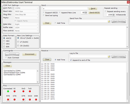
To view the value being reported, you can use the COMs terminal available from within MikroC. It is located here Tools > USART Terminal.

As noted in the values reported, a high value indicates drier soil and a lower value more moist soil.
What Next
Moving forward, we will build up an IoT system that measures soil moisture putting control into the hands of the user.
History
Version 1, First release
