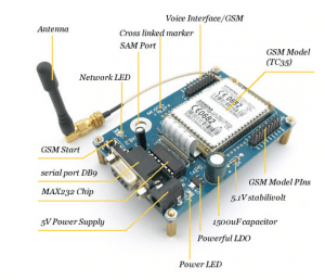
This post summarizes my experiment with GSM SIEMENS TC35 and describes some interesting findings.
Introduction
The GSM SIEMENS TC35 is a portable GSM modem module which can communicate directly with the PC or other microcontrollers using its UART module at a baud rate of 19200bps. It can be programmed to send/receive text messages as well as phone calls by using AT commands. The module has a reasonable power consumption of approximately 150-200mA during calls and 40-50mA when idle with SIM card registered on the network. This article will summarize my experiment with this GSM module and describes some interesting findings.
Board Layout
Top View

Bottom View

The module has four 2.54mm connectors – one for microphone/earphone (voice interface), one for battery supply (see datasheet), one with only VCC/GND pin, and one with some of the repeated pins from the other three connectors.
The onboard MAX232 is connected directly to the 5V power supply while the rest of the board works with 3.3V from AMS1117. My module comes with the provided headphone/mic socket wrongly plugged into the battery slot, causing ^SCTM_A: 2 error at boot up and automatically shutdown of the module because it thinks the battery temperature is high. The onboard battery sockets also have some pins reserved for connection to external RTD sensors for battery temperature measurements.
Interfacing with the Arduino
This section explains how to interface the TC35 module with the Arduino Uno board, ATmega328p processor. Follow the below steps to connect UNO board to GSM SIEMENS TC35 Board:
First, connect TX of UNO board to RX of GSM SIEMENS TC35 Board:

Next, connect RX of UNO board to TX of GSM SIEMENS TC35 Board.

Now connect GND of UNO board to GND of GSM SIEMENS TC35 Board. This makes sure all signals have the same ground reference.

Supply 5V power for UNO board and GSM SIEMENS TC35 Board (or support 5V for UNO Board, then connect power of UNO Board to GSM SIEMENS TC35 Board). Upon applying power, the reset switch on the board must be pressed to power up the module. This is equal to short-circuiting the IGT (ignition) line to GND. The process is described in the Power-On section of the datasheet.

Finally, connect the UNO Board to the PC using USB cable. The datasheet of UNO Board can be found here. Download the necessary code to the UNO Board to communicate with the TC35 module.
If your microcontroller cannot communicate with the TC35 board despite apparently correct connections, try to reverse the TX and RX pins – some cheap TC35 boards might have incorrect labelling for some of the pins.
This is the final schematic connection diagram between UNO Board and the TC35 board:

This picture shows the connection of the serial cable to the TC35 module.

This is the connection of the serial cable to computer’s serial port:

Configuring the Serial Connection
Before continuing, make sure you have inserted an active SIM card into the SIM card holder and press the GSM Start button:

The Network LED will blink at a pattern of 500ms on and 500ms off to indicate that the TC35 is initializing and not yet ready. When the LED blinks at a pattern of 75ms on and 3 seconds off, this means the TC35 modem is ready to be used.
Next, open Hyper Terminal and create a new connection to the correct serial port:

In port settings, set the baud rate to be 9600bps, and flow control to be None (8N1):

Making Outgoing Calls
Before continuing, you may also want to check if your module supports voice call using AT+FCLASS command. On my module, there is no support for voice calls, only fax/data calls, as AT+FCLASS returns only 0/1 and not 8 – so the modem will response with a NO CARRIER unless the SIM card supports fax/data calls.
The following is a a transcript of a serial session to make outgoing calls on the TC35 module using the ATD command to dial a number and ATH to hang up:

Sending Text Messages
The following AT commands demonstrate how to send an outgoing SMS message:
AT+CMGF=1
OK
AT+CMGS=84903167823
OK
>hello world!!!
+CMGS:   8
OK
After sending the AT+CMGS followed by target phone number, type the message followed by Ctrl+Z and the modem will return +CMGS: XXX to indicate that the message has been sent.
Reading SMS Message
The following code is used to demonstrate how to read SMS messages using GSM SEIMENS TC35 SMS Wireless Module.
AT+CMGF=1
OK
AT+CMGR=1
+CMGR: "REC READ", "+84903167823",,"15/09/23,10:37:05+23"
Hello
OK
AT+CMGR=2
+CMGR: "REC READ", "+84903167823",,"15/09/23,10:40:12+52"
Oh, hello
OK
To read a message, send AT+CMGR=<n> where <n> is the memory message position. In the above example, we are reading message 1 and message 2. The first message has content is “Hello” and the second message has content “Oh, hello”.
With the above AT commands, one can successfully program the Arduino or any other microcontrollers to send/receive calls or SMS using the TC35 with little difficulties. For more information on AT commands, read this Wikipedia article. You may also want to read the GSM SIEMENS TC35 Datasheet for further technical details on the TC35 module.
