Introduction
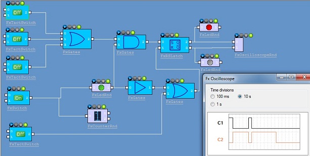
Some time ago, I tried to find a free software tool to simulate a very simple alarm using a small number of gates, without (almost) success. Because I already knew about the FxEngine Framework, I decided to create my gates to simulate my simple alarm. The final aim was to be able to create a sophisticated bit flow using a small number of gates.
As of now, the available types of simple gates are:
ANDNANDORNOR NOTXORXNOR
Also, I wrote a more complicated gate which is an RS latch, and several useful components which include:
- Button
- Tact button
- Constant Bit
- Wires junction
- Multicolor LED
- Alpha numerical counter
- Source clock
- Oscilloscope renderer (CLI demonstration)
About the Alpha numerical counter: I use the bitmap of the http://www.codeproject.com/KB/static/digidisplay.aspx project. Thanks to Nic WILSON for his work.
Background
The main background is, of course, the FxEngine Framework here. To use all plug-ins, you have to download the framework.
Note that the FxEngine Editor is included in the framework installation.
I already posted an article about how to create a plug-in to stream video data from a webcam.
Using the Code
In the zip file, you will find:
- A global Visual 2005 and 2008 project: .\Build\x86-w32\Vc8 and .\Build\x86-w32\Vc9
- All individual projects for each Fx (i.e., plug-in) for Visual 2005 and 2008
The Plug-in Concept
The main Fx concept is each time we receive a new incoming value on an input pin, the Fx has to compute a new value and transmit it to the next Fx in chain. To be more compliant with the real logical circuits, the values in the logic flow are 1 and 0, but we could imagine more complex flows with more than two values.
Write the Plug-in
The Fx writing is quick and simple. The first lines are the DLL main (optional) to handle the DLL_PROCESS_ATTACH message. All other lines describe the plug-in behavior. Each Fx must have a C++ class which inherits one of two C++ interfaces:
To retrieve the class instance, the framework calls the FEF_GetFxBase method.
Both interfaces contain several virtual methods to (over)-write. The interfaces are used to:
- Control the plug-in (init, start, stop, ...)
- Handle the plug-in events like incoming data, pin connection, or new parameters updating
For instance, the control method Stop of the Led plug-in will have the following definition:
Int32 CFxLedRnd::StopFx()
{
if(_FxState != FX_STOP_STATE) {
_pFxState->FxPublishState(_FxState = FX_STOP_STATE);
}
return DeliverSignal();
}
where the method sets the Fx state and delivers the value "0" on its output pin.
The connection event will have the following definition:
Void CFxLedRnd::FxPinState( IFxPin* pFxPin, FX_PIN_STATE PinState )
{
if(PinState == PIN_CONNECTED) {
if(pFxPin == _pFxOutPin) DeliverSignal(); }
else { if(pFxPin == _pFxInPin) {
_bInPinValue = 0;
DeliverSignal(); }
}
return;
}
Where:
- when the input pin is disconnected, we consider "
0" on its input pin and then deliver it on the output. - when the output pin is connected, we have to transmit the current value to the next Fx.
More programming details are available in the FxEngine user guide.
Write the GUI
The gates in the first version (1.1) use the old but very efficient API from Microsoft: the WIN32 API. Each GUI is based on a .rc and a .h file. To make the development easier for me, I used this excellent tool: resedit. The only code I had to add was to handle the GUI events like button, check box, ... This is done by the callback function:
LONG CALLBACK FxWndProc(HWND hwndDlg, UINT uMsg, WPARAM wParam, LPARAM lParam);
About the buttons: Each button has two input pins which are used to define the high and low bit values according to the switch position. But if no signal is connected to them, by default, the high and low bit values are, respectively, "1" and "0".
History
- Version 1.3 (2010.07.12): Added Clock and Oscilloscope Fxs
- Version 1.2 (2010.05.11): Added alpha-numerical counter Fx
- Version 1.1 (2010.04.22): First version
