Introduction
This article is continuation about a HID USB Stack for Microchip PIC16F1455 and the way of communicating with it on Windows Platform. To see the first part click Here
Background
In the first part I have demonstrated how to build and program a generic hid device using Microchip PIC 16F1455 also how to comunicate with windows using a set of components written in C#.
This will show how to use the chip as a Keyboard, Mouse and all combined in a hybrid device covering the following:
- Creation of HID Keyboard with a key and a "Num Lock" status Led
- Creation of HID Mouse
- Creation of hybrid device being Generic HId, Keyboard and Mouse on one chip.
All of the code has been written under MPLAB-X 2.10 for compiler XC8 v1.30.
Using the code
The Keyboard
First we will start with the keyboard. The setup is exactly the same, so the same schematic and design applies. What we are going to change is the firmware on the chip.
Download the following files:
- 16F1455Keyboard.zip -> This is the MPLABX project.
- 16F1455KeyboardHex.zip -> This is the complied Hex of the above
Build the project or use the hax file and burn it to the chip.
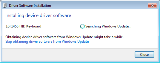
After programming connect it to the computer.
Here is what happened on mine:


Here is what I found under the Device Manager:

Pressing the button will emulate key "A" pressed on the keyboard and will behave just like a real keyboard with repeat etc. Easiest way to test it is by using a notepad. The Led reflects the current status of Num Lock. To test it, check if the num lock status on the device is the same as on your keyboard, then press the key on your keyboard to see if our device reflects the changes.
The Mouse
Now it is time to play with the mouse. The setup is exactly the same, so the same schematic and design applies. What we are going to change is the firmware on the chip again.
Download the following files:
- 16F1455Mouse.zip -> This is the MPLABX project.
- 16F1455MouseHex.zip -> This is the complied Hex of the above
Build the project or use the hax file and burn it to the chip.
After programming connect it to the computer.
Here is what happened on mine:


Here is what I found under the Device Manager:

Pressing the button will emulate the mouse Right Click. To test it just point at something with your mouse and press the button on the device. This will bring a context menu just as if you click a right button. The Led has no use in this example so it just stays on.
The Hybrid
This is where the real fun starts. The setup is exactly the same, so the same schematic and design applies, but for the last time in this article we will change the firmware on the chip.
Download the following files:
- 16F1455HidKeyboardMouse.zip -> This is the MPLABX project.
- 16F1455HidKeyboardMouseHex.zip -> This is the complied Hex of the above
- USB16F1455HidTest.zip -> This is a Visual Studio Project for the Windows Side
Build the project or use the hax file and burn it to the chip.
After programming connect it to the computer.
Here is what happened on mine:


Here is what I found under the Device Manager:

Please note how windows "knows" that this is a multiple interface device. MI_00 is assigned to the first endpoint which is our Generic HID, Keyboard and mouse get their ids MI_01 and MI_02 respectively.
This image shows how nicely they sit under device manager.

You will also be able to find it under devices and printers:

And adjust its properties just like any other mouse and keyboard:

At this stage we have three devices on a single chip and we can utilise and interact with any and all of them at the same time. To quickly demostrate it lets start our windows test program. Get Status button still only tells the device to send its current status, but Toggle Led, all thou it still toggles the led, does it in fundamentaly different way. Effectively the device receives the command and simulates the Num Lock key press on its keyboard interface. This changes the Numlock on all keyboards attached to the host, which makes the host to update all attached keyboards with new status, including our device's Keyboard inteface, which upon reception of the update, sets the led accordingly and reports the new status thru the HID interface. It is a bit long way around but it suits our testing well. The last bit left to test is the button on the PIC. When the numlock led is on it will simulate the A key on the keyboard interface and when the numlock is off it will do the right click on the mouse interface, in both instances reporting back to the HID.
This, i think, nicely demonstrates usage of all interfaces and interaction between them.
Points of Interest
The hybrid was the last model I wrote and during writing the software I have borrowed a lot of code from the other three, mainly to put it together, and while doing so I have discovered that the base stack is still by no means perfect. I had to cheat and fix various bits in "Usb,c" just to make it work ditching some methods of automation that I had in mind when designing the whole lot. I am sure that sooner or later I will have a very good unified base for any device type, where a single replacement of "UsbDescriptors.h" and nothing else will be the only necessary change to make any device desired. Anyone with trained eye and good knowledge of C will spot those almost immediately.
I hope this still remains a good example of how we can play with those chips and have fun with them.
