Introduction
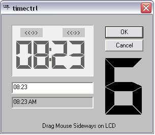
This control is a seven segment LCD like in digital clocks or embedded systems.
Background
I wanted to create a simple control to set date/time quickly by dragging the mouse on the number. It was self evident to make it look like a digital clock. I also wanted it simple to use and simple to deploy, e.g. without installing extra fonts, or making a special installation for the executable.

Using the Code
The Clcd7 class is the heart of it all. The demo application contains a fully functional time setting demo control, where the LCD can be used to set time (the app itself just puts the result in an edit box):
Clcd7 hour1, hour2;
Clcd7 minute1, minute2;
In the IntDialog() function of the parent, you may set operational parameters such as:
m_lcd.SetBgColor(RGB(192, 192, 192));
m_lcd.SetFgColor(RGB(12, 12, 12));
#define WM_OVERFLOW (WM_USER + 1)
#define WM_UNDERFLOW (WM_USER + 2)
#define WM_TCHANGE (WM_USER + 3)
(make sure the messages are unique in your app, or us RegWndMsg)
To capture these messages use:
BEGIN_MESSAGE_MAP(CTimectrlDlg, CDialog)
......
ON_MESSAGE(WM_TCHANGE, lcd_change)
......
END_MESSAGE_MAP()
To capture the message:
void CTimectrlDlg::lcd_change(WORD wparam, LONG lparam)
{
TRACE("lcd change on %d\r\n", wparam);
}
The wparam contains the control id of the LCD that sent the message.
Points of Interest
I used Windows message mechanism to send a message when the LCD has changed. This allowed a very simple code to update the UI feedback and to update the edit box that mirrored the current numbers.
The underflow or overflow messages can be used to couple multiple LCDs together very simply. The principle is as follows:
If LCD1 sends an overflow message -> increment LCD2 .....
if(pMsg->message == WM_OVERFLOW)
{
TRACE("CTimectrlDlg::PreTranslateMessage WM_OVERFLOW on %d\r\n", pMsg->wParam);
if(pMsg->wParam == CONTROL_FOR_LOWER_DIGIT)
{
m_lcd2.num++;
m_lcd.Invaldate();
}
}
The same can be done for the UNDERFLOW as well. When Invalidate() is called, the control may send a message if it overflows. This allows cascading multiple LCDs.
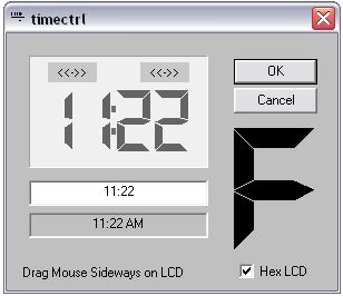
To set the LCD to Hex mode, use:
SetMinMax(0, 15);
SetMinMax(0, 9);

I also made arrangements to set the parameters of the control, sensitive to its Windows creation state. This way, parameters can be set on the pre-creation state without blowing the whole thing up with an ASSERT.
Here is a snippet how:

void Clcd7::SetBgColor(COLORREF col)
{
    bg = col;

    if(::IsWindow(m_hWnd))
        Invalidate();
}
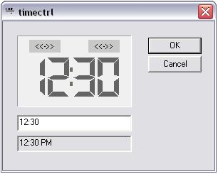
An older version of the control demo:

History
- 16th January, 2008: Initial release
- 18th January, 2008: Added cleaned version of the source (cleaned out *.obj and such)
Notables
I tried using an LCD font as a display for the control. While displaying the font was easy, hit testing on the font, scaling it and magnifying it was harder. The : (colon) was in the wrong place, the gaps did not magnify as nicely as needed, and making the lines thin or fat was not an option. Hence the custom LCD. One cool side effect is that it can be used in the transparency environment.
Thanks for reading.
